

-
1, set the software format, keep consistent with the machine format.
2, restore to the default parameters, set the current software properties, and maintain the same machine.
3, the controller panel settings work positioning mode for software positioning.
4, modify the color of the projection area.
5, start calibration, load and cut the calibration grid line; use the computer keyboard button [Delete] to delete the entire line is not within the projection format and the entire column of calibration points,
Then drag the calibration point to overlap the cutting grid intersection.
6, complete the calibration
7, selected graphics projection
8, box projection graphics, fine-tuning the location of the projection. Press the computer keyboard [arrow keys] can move slowly graphics; press [shift + arrow keys] can quickly move graphics.
9, export the projection graphics, to facilitate the next use.
10, import the saved projection file direct projection.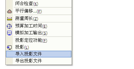
-
1, the first laser installed in the computer software.
2, first refer to the wiring diagram to connect the hardware.
3, then the laser part must be to ensure that the laser power connected to the laser tube, the water tank is open, water cycle, or turn off the laser power switch If you want to carry out the following steps.
4, pull the laser head to the middle of the machine, boot power, observe the laser head back to the origin of the right direction, if not right, immediately press the stop button on the panel.
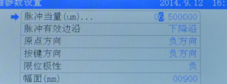
5, press the stop key on the panel + SHIFT key, enter the first axis parameters. Enter the X-axis, modify the X-axis back to the origin direction, if the X-axis back to the origin of the anti-reversal, as long as the anti-change OK, if the key in the opposite direction, the key set the anti-direction.
Machine maximum stroke can also be modified at the same time, the same reason Y-axis is the same. After the change, press the OK button, and then press the reset button, the modified parameters will be valid.
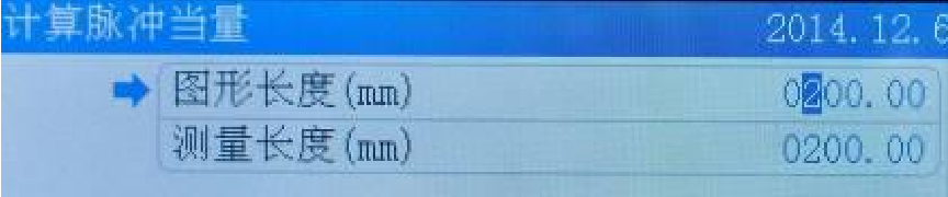
6, modify the pulse equivalent value:
After the software draws a 200 * 200 square, load it into the motherboard, then press the Positioning key, press the start key, let the machine cut the square, and then use the ruler to measure the actual cut value. Press the stop key on the panel + SHIFT Key to enter the first axis parameter.
7, set the size of the machine format, the actual machine how big the table, set the multi-format, to ensure that the machine from the nearest end (origin) to the most remote, the laser head will not hit, this value is the size of the machine can be displayed by the panel XY coordinates to obtain.
note:
1) If the pulse equivalent is less than 1, then you can only modify the driver's subdivision to reduce the driver's subdivision to ensure that the pulse equivalent is greater than one.
2) the polarity of the limit switch We normally recommend to use the normally open sensor to the limit switch is active low after the limit switch. Of course, if the high end of flat, it can only modify the limit polarity.
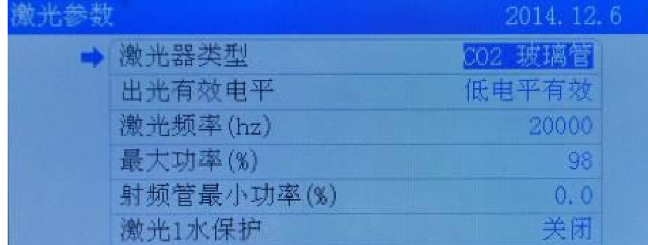
3) Laser power water protection Can directly connect the laser power water protection short circuit, if you want to receive the motherboard, please open the panel on the water protection, the default is off.
-
1, the first laser computer installed in the computer software (laser cad), including the USB driver, you can choose to install Coreldraw, Auto CAD, Illustrator CS plug-in see the instructions.
2, open the package, check the shell and the like, see there is a crush and the like, the machine is drenched over water, wire, gongs like whether there is off, loose, reflective environment, focus is not partial, If too bad, please correct.
3, the installation of a laser tube, connected to a good tank, it must be to ensure that the laser power connected to the laser tube, the water tank has been opened, the water cycle, or put the laser power switch off if you want to proceed to the following steps.
4, pull the laser head to the middle of the machine, boot power, observe the laser head back to the origin of the right direction, if not right, immediately press the stop button on the panel.
5, press the stop key on the panel + SHIFT key, enter the first axis parameters. Enter the X-axis, modify the X-axis back to the origin direction, if the X-axis back to the origin of the anti-reversal, as long as the anti-change OK, if the key in the opposite direction, the direction of the key set anti.
机器最大行程也可以同时修改,同理Y轴也一样,改完之后按确定键,然后再按复位键,修改后的参数则会有效。
6、调节光路,一般新机器发到厂家,长途运输肯定有波动,所以光路都要调一下。检验光路对不对。
7、查验机器的脉冲当量值是否对的(一般情况下是对的)。在软件画一个200*200的正方形后,加载到主板,然后按定位键,再按开始键,让机器切割此方形,然后用尺 测出实际切割出来的值,如果是准确的,那说明机器脉冲当量值是对的,否则进行下面的方法,在面板上按停止键+SHIFT 键,进入第一项轴参数。
8:验证机器幅面大小,机器实际台面多大,请设置多大幅面,确保机器从最近端(原点)跑到最远端,激光头不会撞,这个值就是机器幅面大小,可以通过面板显示的X Y 坐标值获取。
9:以上检测完成,其它可以交付客户使用。
-
Gancheng motion control card, how to set up double-headed mutual transfer function?
Double-head interactive function to open and set, the main three steps, the specific way is as follows:
The first step: the panel to open double-headed mutual transfer settings.
1, hold down the stop key + Shift key at the same time in the panel, the following interface appears:
The company is located in:
2, select the first six long mutual transfer settings, click to enter the setup interface. Set the number of reciprocal axes to 2, ZX axis spacing is reset after the two laser heads together the minimum.
Step 2: Set the pulse equivalent of Z axis by jogging control.
1, the first point shot, write down the location of mutual head RBI.
2, press the menu button to enter the system menu interface, select "jog control" option.
3, by up and down keys or left and right keys to set the jogging distance of 200MM.
4, press the button to move the Z axis jog, and then click the left or right button, and then press the exit button, and then click the button. Hand out the amount of the first two points of mutual transfer of the first point of shooting distance.
5, press the stop key + Shift key to enter the axis parameters, modify the pulse equivalent of the Z axis.
The length of the graphic is the distance just moved (200mm); the measurement length is the actual distance just before measuring two points. After input, press the OK button, then press the reset button OK.
The third step: software layout.
1, the array parameters set typesetting map, first into the typesetting a single graphic, and then find this symbol to fill in the number of columns to be processed, the number of rows, pay attention to the graphics must be a single graphic is a solid line, the other is all dashed.
Note that the use of line mirroring and column mirroring, such as: cut 6 column diagram, sometimes select the column mirror, resulting in a cut two, the other cut four reasons for this. Because sometimes through the mirror, the map is too deep, in order to avoid switching materials, then the equivalent of two figures into a map.
2, if the material there is spare part, in order not to waste material, you can choose to cut into trim.
3, import or draw their own graphics to be processed, and then edit the point of conversion into scrap.
As shown, the red rectangle is the scrap
4, in the panel can choose cutting near the corner, so which corners near the head, which head will be cut in the past.
5, the customer on the laser head to go the path requirements, for example: the origin of the machine in the upper right corner, the laser head from the top right corner of the table to start cutting, then press the following actions: First, the machine zero position and page zero position settings, such as Picture shows:
Then, the relative position of the graph:
Then, click to load the current document, re-optimize the cutting path, as shown:
Inter-block spacing refers to the height of a single graphic in the Y-direction, which is slightly larger than the height of a single graphic in the Y-direction. Finally, the laser head to the bottom right corner of the platform, press the positioning key (usually select the panel key positioning mode), even if the setting is completed.
Similarly: 4 sets of mutual transfer of more V and W axis, only need to shift the number of axes selected as 4, then add the ZV spacing and VW spacing OK.
-
The first step, check the machine's mechanical parts are intact, including:
1 platform is flat, cut a 400 * 400mm square, the amount of diagonal is equal.
Belt tension is reasonable, the belt is missing teeth.
3. Whether the guide is smooth, there is no foreign body in the guide (impurities and the like). If not smooth, students need to use cloth polishing cloth, marked with oil, foreign body to be cleared.
4. Lock motor, belt, rail gong wire is loose, if loose need to tighten.
5. Make sure the machine does not have the above problems, the next step.
The second step, debugging software section
1. Make sure the user parameters are debugged properly. It is not clear how to debug the parameters can be modified using a key, select the slow parameter on the panel, the speed factor is set to 0.5.
2. Processing speed is set at 10-30mm / s, if the cutting speed is not good, please re-adjust the mechanical part, it is sure the machine is not adjusted.
3. After loading the software select this file, to compensate for the lack of machinery.
4. Repeatedly cut the same file several times, if the return point a bit biased, and sometimes can be modified, as shown:
There is currently a rising edge of the outskirts, can be changed to fall along the effective, on the contrary. Then reset the machine. If it is a servo drive, be sure to use the shield with a layer of the screen, and the shield should be connected to the motherboard GND.
5. For cutting speed caused by the cutting effect is not good, you can increase the drive current.
-
Different special functions, different ways to open.
1, clothing marked the direction of opening and marking, as follows:
The company is located in:
2, panel to modify factory parameters: stop key + SHIFT key.
3, panel test I / O function: Press and hold the stop button, press the second menu button.
4, Jog Function: Press and hold the stop key, then press the left or right key or up and down, you can let the laser head slowly move.
5, Feeding axis manual movement function: For PLUS card, press C key and 0 key, you can move the feeding axis.
-
(1) The software zero position must be consistent with the actual machine installation origin limit switch, the upper right corner must be set in the upper right corner, not free to change.
(2) If it is not a machine with automatic feeding, it is not a double-headed asynchronous machine. In the additional function parameter setting interface, please set as follows:
(3) The relative position of graphics must be set correctly, it is best to set the same position with the machine zero, such as machine zero is the upper right corner:
(4) Positioning mode in the panel generally select the button positioning. Press the menu button on the panel, and then select the seventh "basic parameter settings" press the OK button, and then select the first one, the working mode configuration.
(5) In the normal main interface of the machine, press the OK key, move the cursor to the file name with the up and down keys (note that the file name is changed to a blue background to the file name), and then press the OK key.
Then, enter the file properties settings, view the size of the current processing file size
X size refers to the size of the overall processing graphics X direction, the same Y the same
Then observe the laser head stopped at a certain position, you can see the X Y coordinates
Estimated laser head from this position to the right side of the machine graphics enough for the length of the graphics, if enough, in the panel by the positioning key to complete the operation, the problem of super format to solve, and vice versa can only move the laser head near the origin of the direction, and then Press the navigation key.
When the laser head moved to the limit switch near the origin, panel coordinates show XY coordinates are 0, and then press the positioning key, if at this time or prompt graphics out of bounds, that the size of the graphics must have exceeded the size of the machine format, then the processing Graphics machine can not be processed. (Of course, you can also move the laser head to the farthest end of the limit switch from the origin, through the panel coordinates to identify the size of the machine format, provided that X, Y pulse equivalent to be correct)
If you can understand the position of the laser head with respect to the position of the figure, and always remember that the three points are consistent, you can flexibly and freely change the blue point in the software, that is, the panel displays the blue point of the figure and the I laser head.
(6) If the machine with automatic feeding, directly open the super-format cutting.
That machine positioning must be set at the origin of the machine in the same direction
(7) The general default is the automatic positioning off when the super-border, if opened here, the software automatically according to the size of the graphics, automatically find the location of the cut and will not prompt the graphic super-world
(8) When engraving graphics, the laser head must not be too close to the machine's side, the general should set aside 20mm distance.
